Obscura
A collaboration with Eden Harrison for the Gizmo course, Imperial College & Royal College of Art.
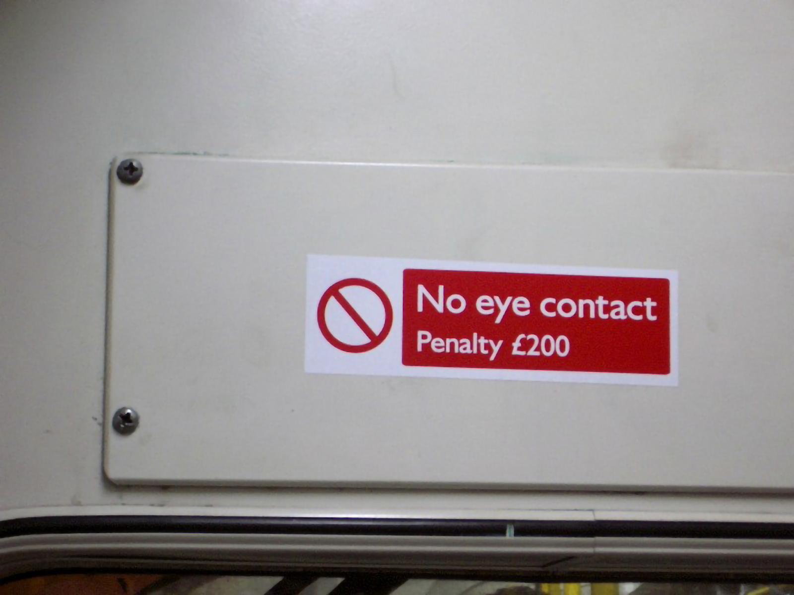
Obscura explores the awkwardness produced by direct eye contact in public transport. We built glasses that detect the surrounding gaze direction and help the wearer avoid unwanted eye contact. A short clip is here ↗.
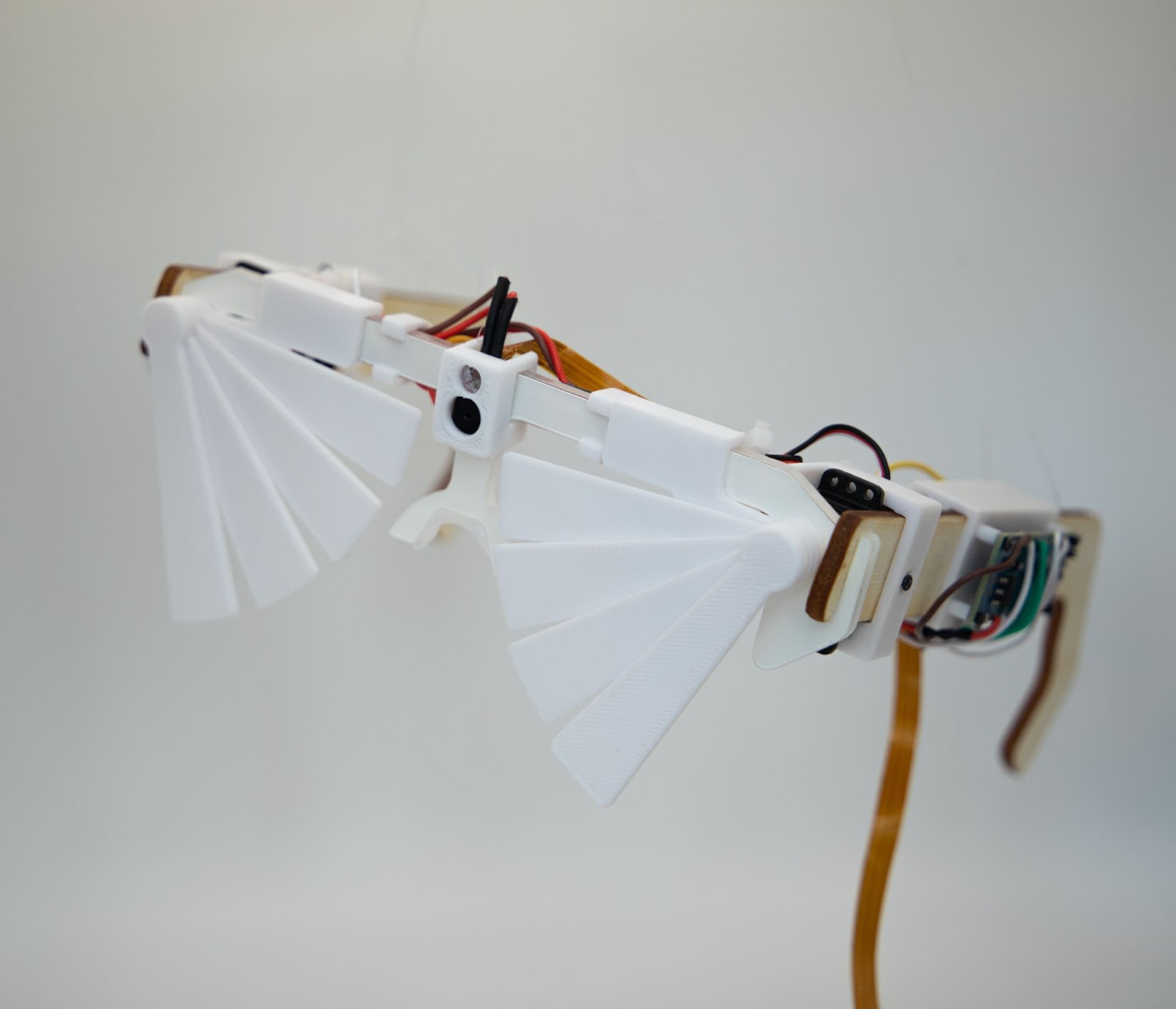
Parts
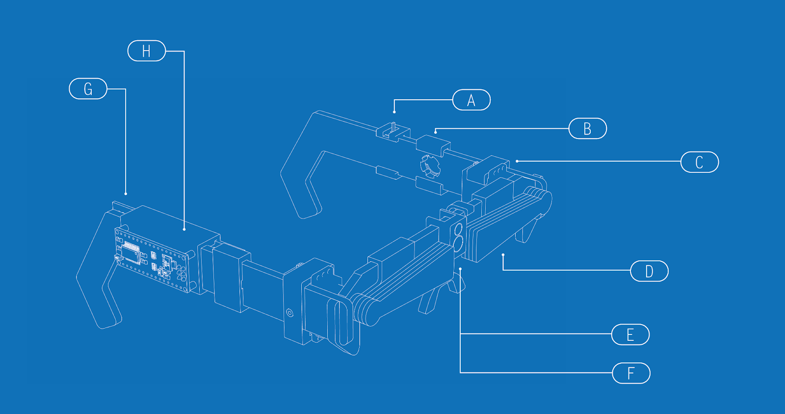
Function A: Alert
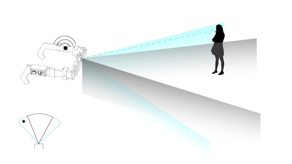
When the perpetrator is on the left or right of the frame, the corresponding vibration motor buzzes, alerting the wearer to the attempt at eye contact. They can then decide to avoid or engage as they wish.
Function B: Hide
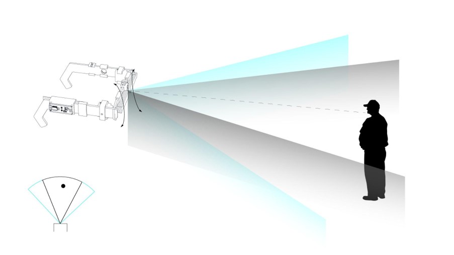
When the perpetrator is centered in the frame and the 'hide' function is engaged, the wings descend to obscure direct eye contact, lifting again after four seconds. With 'hide' disengaged, nothing happens.
Computer Vision Pipeline
A pre-trained face detector locates each face in the frame, mapping 68 landmarks to describe it.
For each face, the eyes are extracted from the landmarks. Contour detection on the thresholded eye image finds the iris; an ellipse is fitted to locate its center. The midpoint between irises is referenced from the nose tip.
The 68 landmarks are mapped to 3D coordinates from an average head model. Perspective-n-point then yields the rotation and translation vectors using the camera's intrinsics.
Classification & Architecture
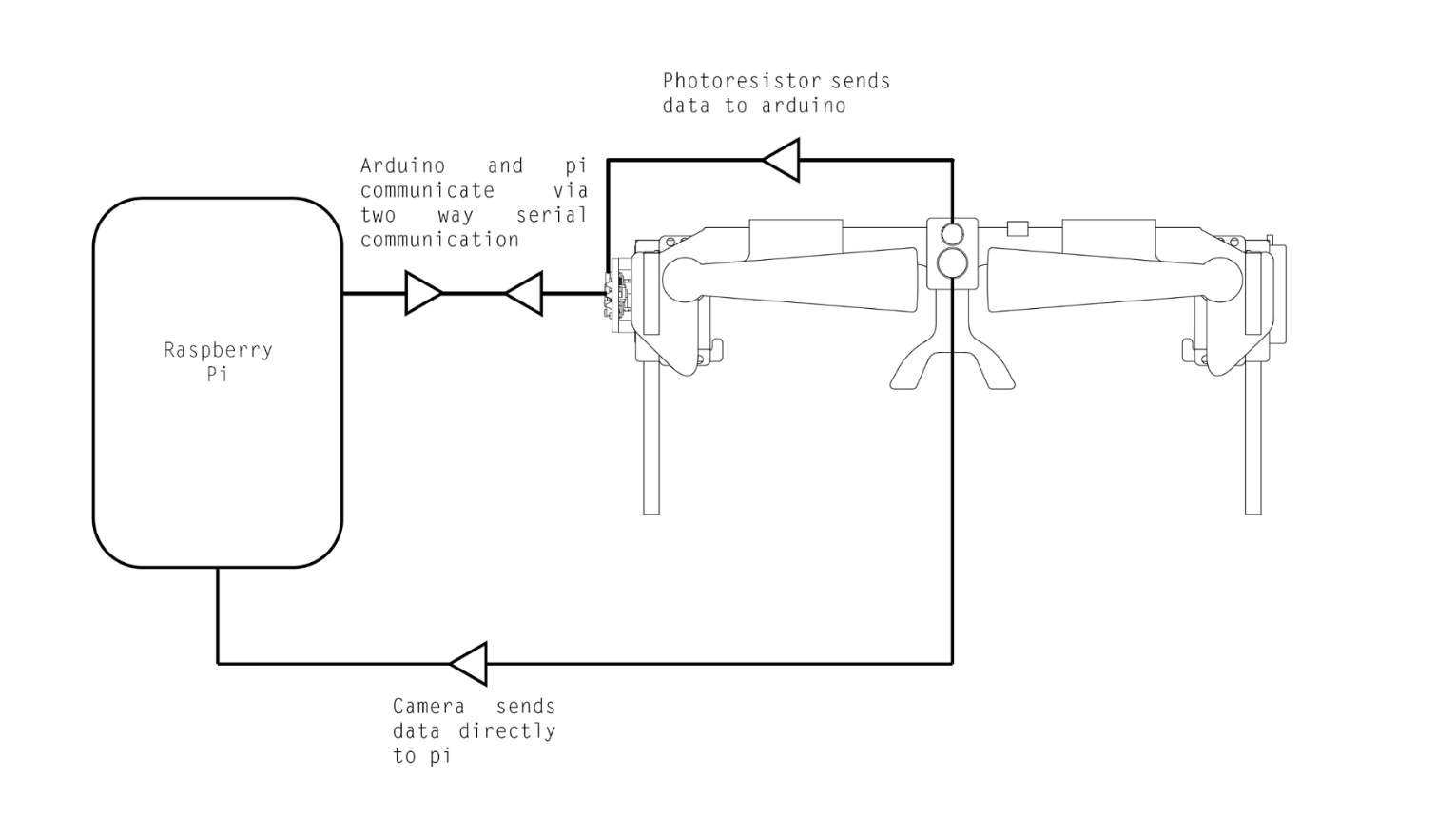
The iris-midpoint, head-rotation and head-translation vectors are combined and classified as 'directed toward camera' or 'not' via an SVM, trained on a labelled set of captured images and exported as a pickled model that runs live on the Pi.
Output travels from the Raspberry Pi to the Arduino over serial; the Arduino executes the corresponding action on the shades and motors.